
O-Ring Gland & Groove Design Guide
Reduce Leaks, Improve Seal Life & Simplify Assembly
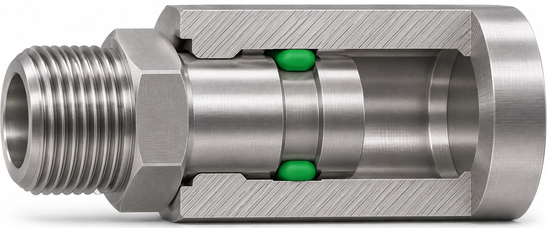
A standard O-ring can match the size chart and still leak in the assembly. The groove and mating surface control how much the ring compresses, where it makes contact, and how much room it has to deform. That’s why O-ring gland design and O-ring groove design deserve the same attention as size and material selection.
Finn Global Supply helps OEM engineers, maintenance teams, and buyers evaluate the seal as part of the assembly. Whether you’re designing a new hydraulic component, replacing a seal in existing equipment, or investigating a recurring leak, start with the drawing and the operating conditions. Our team can review how O-ring squeeze, stretch, O-ring groove fill, and clearance affect static and dynamic O-ring seals before you commit to a part or tooling.
O-Ring Gland Design: Start With the Assembly
The groove is the recess that holds the O-ring. The gland is the space that contains it once the mating parts come together. On a drawing, groove depth may look like the controlling dimension. In the assembled part, the position of the mating surface determines the actual space available to the seal.
Start by identifying where the groove is cut and which surfaces move during operation. A flange that bolts together and stays fixed has different design requirements from a rod that cycles thousands of times. If you still need to identify the ring, use our O-Ring Size Charts & Material Specifications to check the inside diameter and cross-section.
Face, Piston & Rod O-Ring Grooves
| Gland type | Where the groove sits | What to check first |
|---|---|---|
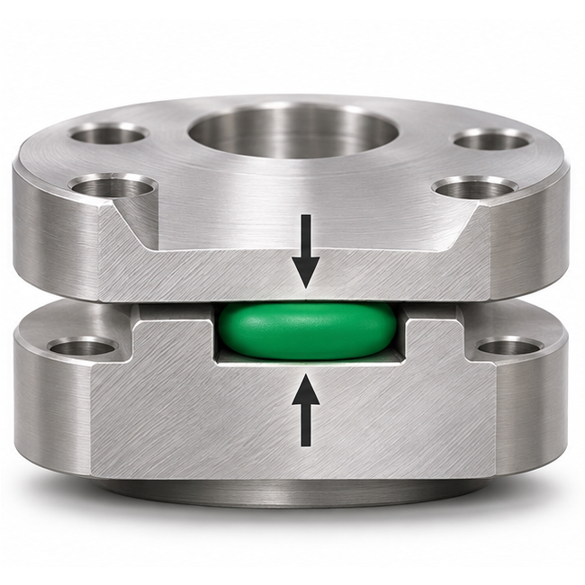
| Face seal | In the face of a flange, cover, or mating plate. The seal compresses axially as the parts close. | Identify whether pressure acts from inside or outside the ring. Check assembled gland depth and the flatness of the mating faces. |
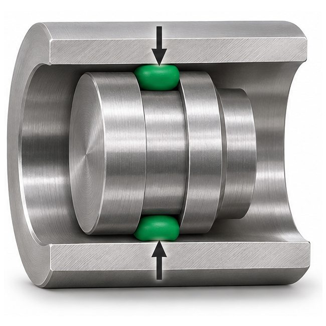
| Piston seal | Around the outside of a piston. The seal compresses radially against the bore. | Check the bore and groove diameters, installed ring stretch, and the maximum clearance on the side where pressure can push the seal. |
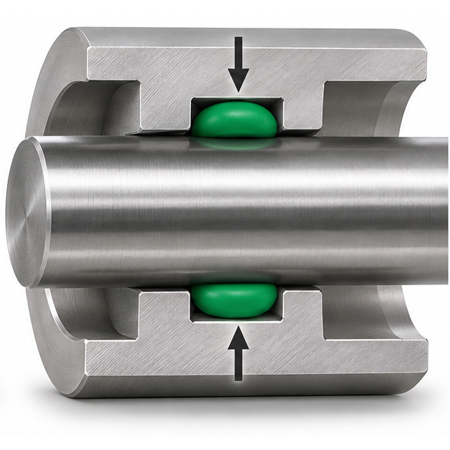
| Rod seal | In an internal housing groove. The seal compresses radially against the outside of a rod or shaft. | Check rod diameter, installation access, and surface finish. For a moving rod, include stroke, speed, and cycle rate. |
Face
Axial compression
Piston
Radial compression
Rod
Radial compression
O-Ring Squeeze, Stretch & Groove Fill
Squeeze is the reduction in the cord’s cross-section along the direction of compression when the gland closes. Too little squeeze can leave inadequate sealing contact. Too much can increase assembly force, friction, or wear. Check the range at both ends of the tolerance stack: the smallest ring in the deepest assembled gland, and the largest ring in the shallowest gland.
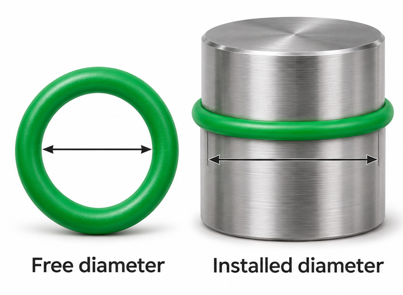
Stretch is the increase in the O-ring’s inside diameter when it fits over a groove or mounting diameter. An O-ring that stretches can become thinner in cross-section, which changes the squeeze you calculated from its free-state dimensions. Check how far the ring must stretch during installation as well as how it sits after assembly.
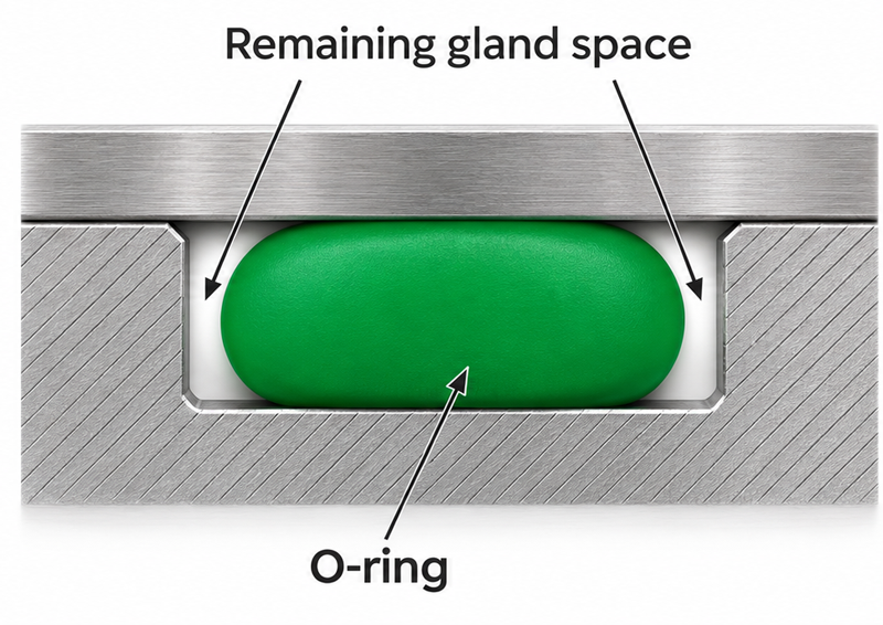
Groove fill compares the volume of the O-ring with the space available in the gland. The ring needs room to change shape as it compresses. Account for tolerances, any backup ring, and changes in seal volume that may occur with heat or fluid exposure.
O-ring Stretch
Grove Fill
Example: How Gland Depth Changes O-Ring Squeeze
| Assembled gland depth | Cord compression | Calculated squeeze |
|---|---|---|
| 2.40 mm | 0.60 mm | 20% |
| 2.55 mm | 0.45 mm | 15% |
| 2.70 mm | 0.30 mm | 10% |
Illustrative calculation for a 3.00 mm free cross-section. Assumes no installed stretch or swelling.
Gland depth vs. O-Ring squeeze
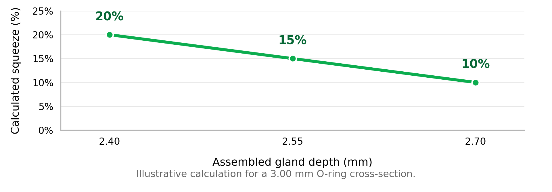
The example shows why two assemblies using the same O-ring can compress it differently. Use these values to understand the calculation. For an actual design, confirm the target range and tolerances for the gland type, compound, and service conditions.
Static and Dynamic O-Ring Seals
A static seal works between surfaces that stay fixed relative to each other in service, such as a cover or flange. Review the assembled gap, pressure direction, and how evenly the mating parts close around the seal.
A dynamic seal works against a moving surface, such as a reciprocating piston or rod. Motion introduces friction and wear, so include surface finish, travel, speed, lubrication, and cycle rate in the review. If you’re evaluating assembly lubrication, see Preparation-O O-Ring Installation Lubricant.
Clearance, Extrusion & Installation Details
Pressure can push an O-ring into the clearance between mating parts. If you see material bitten away along an edge of a failed seal, check the pressure direction, actual running clearance, and whether the parts deflect under load. Depending on the design, a change to the clearance, a different compound hardness, or a backup ring may be worth reviewing.
Also check how the ring gets into the groove. A sharp corner, exposed thread, or poor lead-in can damage the seal before the assembly ever runs. Include the installation path, groove radii, and relevant surface finishes on the drawing, especially if the installer can’t see the ring once it’s in place.
Request a Seal Design Review
Send FGS the groove and mating-part drawings, the O-ring size or part number, and the operating conditions. Include the media, temperature range, normal and peak pressure, and any movement. If you’re replacing a failed part, photos of the seal and the groove can help show where the issue started.
If your project calls for a custom diameter, an unusual compound, or a change to an existing assembly, our Engineering Seal Design team can help you identify what to confirm before you order.